Die casting mold design is the engineering of the hardened steel tool that shapes molten metal under high pressure â covering the cavity and core inserts, the gating and runner system, vents and overflows, cooling channels, the ejection system, and any slides needed to release undercuts. The decisions made here, before any steel is cut, lock in most of a part's unit cost, quality ceiling, and production stability.
A buyer can influence more of the final part price at the mold design stage than at any later negotiation. This guide walks through what a die casting mold contains, the design decisions that matter, tool steel and mold life, and what drives tooling cost â so you can review a mold proposal the way an engineer does. For the production side of the process itself, see our overview of the die casting process.
What Is a Die Casting Mold?
A die casting mold is a reusable, precision-machined steel tool that forms metal parts by receiving molten alloy injected under high pressure, holding it until it solidifies, and then releasing the finished casting. In production the mold works in a repeating cycle: the two halves close and lock, metal fills the cavity in milliseconds, cooling channels pull the heat out, and the moving half opens so ejector pins push the part free. One mold repeats this cycle tens or hundreds of thousands of times, which is why its design quality shows up in every single part.
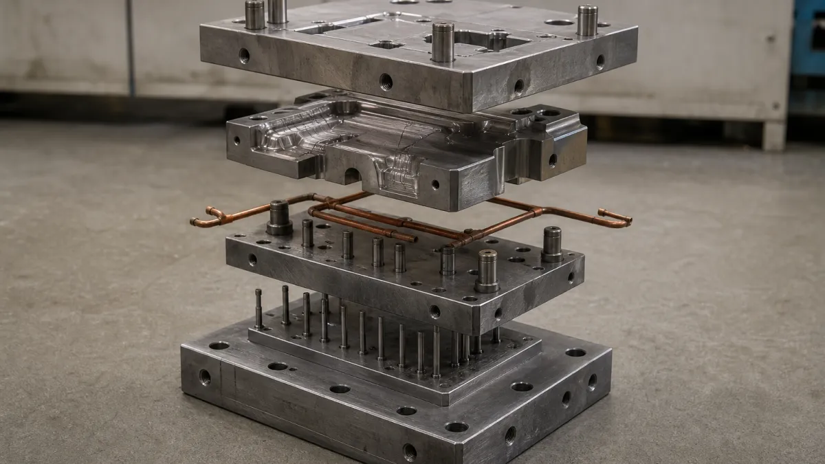
Core Components and What Each One Does
- Cover die (fixed half). Mounts to the stationary platen and receives metal from the shot system through the sprue or biscuit.
- Ejector die (moving half). Opens with the machine and carries the ejector pins that push the casting off the core.
- Cavity and core inserts. Hardened steel blocks that form the part's outer and inner geometry; usually replaceable so worn or modified areas can be swapped without rebuilding the whole mold.
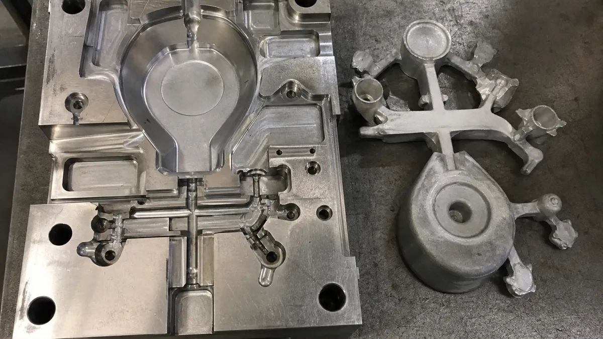
- Runner and gate system. Channels that deliver metal from the shot sleeve to the cavity; the gate controls fill speed, direction, and turbulence.
- Overflows and vents. Catch the first, coolest metal and give trapped air an escape path at the last-to-fill zones.
- Cooling channels. Drilled water or oil lines that hold die temperature steady and set the pace of the cycle.
- Ejection system. Pins, sleeves, and return mechanisms sized to strip the part without bending it.
- Slides and lifters. Moving cores that form undercuts, side holes, and threads, then retract before ejection.
- Mold base and guide system. The frame, guide pillars, and support plates that keep both halves aligned under clamping force.
Common Types of Die Casting Molds
Molds are classified by cavity layout, production stage, and construction. The choice affects both tooling price and piece price, so it belongs in the early quotation discussion:
| Type | How It Works | Best For | Cost Impact |
|---|---|---|---|
| Single-cavity | One part per shot | Large parts, moderate volumes | Lowest tooling cost, higher piece price |
| Multi-cavity | Several identical parts per shot | Small parts at high volume | Higher tooling cost, lower piece price |
| Family mold | Different parts in one shot | Mating parts with matching volumes | One tool instead of several; demands balanced filling |
| Prototype / soft tooling | Simplified construction, shorter lead time | Design validation before production tooling | Low upfront cost, limited shot life |
| Unit die | Standard base with interchangeable inserts | Product families of similar size | Shared base cuts cost of later variants |
Key Design Decisions in Die Casting Mold Design
Each decision below interacts with the others. Treating them as one system, rather than a checklist of independent features, is what separates a mold that runs stable for years from one that needs constant correction.
Matching the Mold to the Machine
Mold design starts from the target machine, not from the part drawing alone. Three machine parameters set hard boundaries. Clamping force must exceed injection pressure multiplied by the part's projected area â a housing with a 200 Ã 150 mm projected area filled at 70 MPa needs roughly 210 tons of clamping, so it runs on a 280T or 400T machine with margin, never a barely sufficient one. Tie-bar spacing and platen size cap the mold footprint. Shot capacity limits how much metal each cycle can deliver, which fixes the runner and biscuit design. Because we operate twenty machines from 160T to 1650T, this matching step is a routine part of our mold proposals: the mold is designed for a specific machine on our floor, with its locking force, platen, and shot sleeve already known.
Parting Line and Draft
The parting line decides where the two halves meet, where a faint witness line is acceptable, and which side holds the part after opening so ejection works. Place it where flash can be trimmed cleanly and away from cosmetic or sealing faces. Walls parallel to the opening direction need draft so the part releases without drag: around 1â2° on outside surfaces and roughly double that on inside surfaces for aluminum, while zinc releases on as little as 0.5°. Zinc's forgiving draft and thinner castable walls are covered in our zinc die casting design guide.
Gating, Runners, and Overflows
The gate is the single most influential feature for internal quality. Its location sets the fill direction, its cross-section sets the gate velocity â typically 20 to 60 m/s for aluminum â and both decide whether the cavity fills in a controlled front or a turbulent spray that folds air into the metal. Runners should feed every region at balanced times, and overflows belong at the last-to-fill zones to collect cold metal and vented gas. How the gate and shot system behave inside a full production cycle is detailed in our aluminum die casting process guide.
Cooling and Thermal Balance
Cooling channels do two jobs: they set the cycle time, and they keep die temperature uniform enough that the part shrinks evenly. Hot spots near thick sections or the gate area invite soldering and shrinkage porosity; cold zones cause poor fill and surface flow lines. Channel layout follows the part's thermal map â closer spacing and higher flow where heat concentrates â and the layout is verified during trial with temperature measurement, then adjusted before serial production.
Ejection System
Ejector pins should sit on ribs, bosses, and other stiff features, spread so the part strips straight off the core without bending. Pins on broad cosmetic faces leave visible marks, and pins near hot, thin areas can push through a part that has not gained enough strength. The acceptable size and position of ejector marks â commonly within about 0.4 mm raised or recessed â should be agreed on the drawing before mold design freezes, because moving a pin afterward means rework on hardened steel.
Slides, Lifters, and Undercuts
Every undercut needs a moving mechanism, and every mechanism adds tooling cost, cycle time, and a wear point that needs maintenance. Before accepting a slide, review the alternatives in order: rotate or relocate the feature into the opening direction, convert it to an open slot, cast a pilot feature and finish it by machining, or use a loose insert for low volumes. When a slide is unavoidable, its locking and wear surfaces deserve the same engineering attention as the cavity itself.
Mold Flow Simulation
Simulation moves trial-and-error off the shop floor. Before steel is cut, filling and solidification software predicts flow fronts, air traps, and hot spots, letting the designer reposition gates, overflows, and cooling lines while changes are still cheap. Our mold team runs this step on JSCAST casting simulation software as standard practice, so the first trial shot starts from a verified design.
Tool Steel and Mold Life
Die casting molds are built from hot-work tool steels that survive repeated contact with molten alloy at 660â700 °C for aluminum. The grade chosen sets the ceiling on mold life, and life is what turns tooling price into cost per part:
| Steel Grade | Working Hardness | Typical Life (Aluminum) | Relative Material Cost |
|---|---|---|---|
| H13 (ASTM A681) | 44â48 HRC | 80,000â150,000 shots | 1.0Ã (baseline) |
| SKD61 (JIS) | 44â48 HRC | 60,000â120,000 shots | 0.85â0.95Ã |
| 8407 (premium H13) | 46â50 HRC | 150,000â300,000+ shots | 1.3â1.8Ã |
| DIEVAR | 46â50 HRC | 200,000â400,000+ shots | 1.6â2.2Ã |
The grades share similar chemistry; the price gap buys purity control and heat treatment consistency, which is what resists heat checking and erosion over long runs. H13 covers the majority of programs; premium grades pay back when lifetime volume is high or the cavity geometry punishes the steel. Zinc dies live far longer â often past a million shots â because zinc melts at roughly half the temperature of aluminum and barely attacks the cavity surface.
Steel choice is only the start. Under an IATF 16949 quality system, tooling is managed as a controlled asset: each mold carries a documented history of shots, maintenance, and repairs, with preventive maintenance scheduled before wear turns into scrap. That discipline routinely decides whether a mold reaches the upper or lower end of its rated life.
Die Casting Mold Cost: What Drives the Price
Production die casting molds typically run from about $5,000 for simple small tools to $50,000 and beyond, with most industrial programs landing between $15,000 and $35,000. The price is engineering hours and machining hours more than steel:
| Cost Component | Typical Share | Main Drivers |
|---|---|---|
| Design and simulation | 5â15% | Part complexity, simulation depth |
| Tool steel and heat treatment | 10â25% | Mold size, steel grade |
| CNC machining and EDM | 40â60% | Geometry complexity, tolerances, slides |
| Surface finishing | 5â15% | Cosmetic and texture requirements |
| Trial and debugging | 10â20% | Optimization iterations to stable production |
Comparing two mold quotes on price alone misleads, because the quote hides two variables that determine the real cost: expected shot life and scrap rate. Convert each quote to cost per shot and adjust for the parts each tool will actually deliver:
Mold cost per good part = tooling price ÷ (expected lifetime shots à (1 â scrap rate))
A $20,000 mold rated for 80,000 shots at a 5% scrap rate costs about $0.26 of tooling per good part. A $40,000 mold rated for 250,000 shots at a 1.5% scrap rate costs about $0.16. The expensive tool is the cheaper one â before counting the downtime and rework the unstable tool would add. Ask every bidder to state expected life and the design basis behind it; the answer tells you how much engineering is actually inside the quote. For how tooling amortization fits into total piece price, see our aluminum die casting cost breakdown.
How Mold Design Affects Casting Defects
Most recurring casting defects trace back to mold design decisions more often than to machine settings. The mapping below is the same one engineers use when a defect appears in production:
| Defect | Common Mold-Related Cause | Design-Stage Check |
|---|---|---|
| Gas porosity | Weak venting, turbulent gate entry, misplaced overflows | Simulate fill; place vents and overflows at last-to-fill zones |
| Cold shut / misrun | Long flow paths, unbalanced runners, cold die zones | Balance runner fill times; verify thermal layout |
| Flash | Parting-line wear, weak support, die deflection | Check clamping margin and support pillar layout |
| Soldering | Persistent hot spots, direct metal impingement on the cavity | Redirect gate impingement; add local cooling |
| Ejector damage / drag marks | Insufficient draft, poor pin placement | Confirm draft on deep features; pin on stiff geometry |
Inspection requirements also belong in mold design, not after it. The datum scheme used for CMM measurement, the surfaces allowed to carry ejector marks, and the machining stock left on sealing faces all have to be fixed before the cavity is machined. In our production those features are verified with Zeiss coordinate measuring machines and X-ray inspection, and the measurement plan is agreed while the mold is still on the drawing board.
What to Prepare Before Requesting a Mold Quote
A complete RFQ package lets the tooling engineer price the mold accurately instead of pricing the unknowns. Prepare:
- 2D drawings with tolerances, critical datums, and GD&T callouts
- A 3D model in STEP or IGES format
- Alloy specification and any customer material standard
- Estimated annual volume and total lifetime volume â these drive cavity count and steel grade
- Surface finish and cosmetic zone requirements
- Secondary operations: machining, tapping, inserts, assembly
- Inspection requirements such as leak testing, CMM reports, or X-ray
- Mold ownership, maintenance, and transfer terms
At Meituo, mold design and mold making happen in the same facility as casting production: our mold engineering center works in UG for 3D design and JSCAST for casting simulation, supported by nearly 30 CNC machining centers and EDM machines, and every mold is built for a specific machine in our 160Tâ1650T die casting fleet. Send your drawings and volume estimate â our engineers will return a DFM review with the mold concept, cavity proposal, and an honest read on what your part will cost to tool.