Most die casting problems are paid for twice — once on the drawing, and again when the mold has to be reworked. A 5 mm wall where 2.5 mm would do stretches cycle time and traps shrinkage porosity; a degree of missing draft drags the part across the die at every shot. This guide puts working numbers on the drawing stage: wall thickness, draft, tolerances, and feature geometry for aluminum parts, so the design that reaches tooling is already manufacturable.
Die casting design (DFM, design for manufacturability) is the practice of shaping a part's geometry, tolerances, and alloy choice so it can be cast consistently, ejected cleanly, and machined economically before any mold steel is cut.
What Are the Core Design Guidelines for Die Casting?
Every detailed rule in this guide traces back to six principles:
- Uniform wall thickness. As thin and even as the alloy and part size allow; thick sections trap shrinkage porosity and stretch cycle time.
- Draft everywhere. Every surface parallel to the die opening direction needs it: walls, cavities, ribs, bosses, lettering.
- Generous fillets. Sharp inside corners concentrate stress in the part and accelerate thermal fatigue cracking in the die steel.
- Geometry that opens in one direction. Undercuts and side features force slides, which add tooling cost and cycle seconds.
- Tolerances matched to the process. As-cast NADCA grades by default; tight numbers only where function demands them, with machining stock planned.
- Decide with the die caster before tooling. Parting line, ejector positions, and gate side are nearly free to change on paper and expensive afterward.
The sections below follow the order you actually make these decisions: alloy first, then wall thickness and draft, then feature details, then the tooling interface and tolerances, and finally finishing and the DFM review.
Choosing the Right Aluminum Alloy for Your Part
Alloy choice is a design decision, because each grade sets different limits on minimum wall thickness, strength, and corrosion behavior. Four alloys cover most aluminum die casting work:
| Alloy | Character | Min. Practical Wall | Pick It When |
|---|---|---|---|
| A380 | The industry workhorse; best combination of castability, strength, and cost | ~1.5 mm | Default choice for housings, brackets, covers at volume |
| ADC12 (≈A383) | Slightly better fluidity and die-filling than A380; dominant grade in Asian supply chains | ~1.5 mm | Thin or intricate geometries, high-cavity tooling, Asian sourcing |
| A360 | Lower copper, higher corrosion resistance and pressure tightness; harder to cast | ~1.25 mm | Corrosion-sensitive or leak-tight parts that justify a higher scrap risk |
| AlSi10Mg-class (low Fe) | High ductility structural variants, weldable | ~1.5–2.0 mm | Structural parts with elongation requirements |
A380 and ADC12 overlap heavily — if your drawing says A380 and your supplier runs ADC12, the substitution is usually sound, but confirm it against the mechanical requirements in writing. A356 and LM25 belong to gravity and sand casting; their low iron content promotes soldering to die steel under high-pressure injection, so they are not interchangeable with the grades above. High-silicon alloys also wear cutting tools faster, which matters if the part needs extensive secondary machining. For the default choice in depth, see our A380 aluminum alloy guide.
Wall Thickness: Recommended Ranges and Uniformity Rules
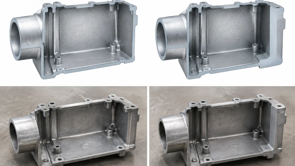
Wall thickness sets fill behavior, solidification time, cycle time, and porosity risk at once. Growing a wall from 2.5 mm to 5 mm typically adds 15–25% to cycle time and invites shrinkage porosity at its core. Recommended aluminum walls scale with part size, measured by the projected area of the casting at the parting line:
| Part Size (Projected Area) | Recommended Nominal Wall | Achievable Minimum (Local) |
|---|---|---|
| Small, under 25 cm² | 1.0–1.8 mm | ~1.0 mm |
| Medium, 25–100 cm² | 1.5–2.5 mm | ~1.2 mm |
| Large, 100–400 cm² | 2.0–3.0 mm | ~1.5 mm |
| Very large, over 400 cm² | 2.5–3.5 mm | ~2.0 mm |
Keep thickness variation within about 1.5× between adjacent sections, with gradual transitions where change is unavoidable. A thick pad surrounded by thin walls solidifies last and shrinks into a void — core it out or split it into ribs. Where a boss genuinely needs more metal, pocket it from the back (metal savers): same stiffness, smaller hot spot, less mass.
What production can actually hold: our practical minimum wall for aluminum die castings is about 1.0 mm, versus 0.3 mm for zinc, and we run appliance ducts at 1.8 mm wall with flatness held within 0.7 mm. Zinc's superior fluidity explains the gap — the zinc die casting design guide covers that geometry envelope in detail.
Draft Angles: Rules of Thumb and NADCA Formulas
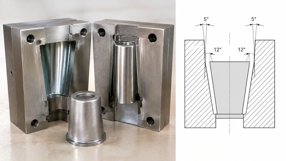
Aluminum shrinks onto the cores that form internal features — solidification shrinkage runs about 0.4–0.6% by volume — so inside surfaces grip the tool while outside surfaces pull away from it. That is why inside draft must be roughly double outside draft:
| Feature | Typical Minimum Draft | Notes |
|---|---|---|
| Outside walls | 1° | 0.5° possible on short, smooth surfaces |
| Inside walls and cavities | 2° | Shrinkage grips the core; never go below 1° |
| Deep pockets (per 25 mm of depth) | Add ~1° | A 50 mm deep cavity typically needs 3–4° |
| Textured surfaces | Add ~1° per 0.1 mm of texture depth | Texture acts like thousands of tiny undercuts |
| Cast lettering and logos | 10° or more | Raised letters eject easier than recessed ones |
| Ribs and ejector-pin pads | 1–1.5° | Deep ribs need the upper end |
The NADCA guideline expresses the same logic as a formula: draft grows with feature depth and surface roughness. Draft-free surfaces are achievable with tighter die fits and polishing, but flag them on the drawing so it belongs in the quote, not in a surprise at mold trial.
Fillets, Ribs, and Bosses: Proportion Rules That Prevent Defects
Fillets, ribs, and bosses all follow simple proportions derived from the nominal wall — get the proportions right and most localized defects never appear. The thermal logic behind every rule: any feature that locally doubles the metal volume solidifies late and shrinks into a void.
| Feature | Recommended Proportion | What Goes Wrong Otherwise |
|---|---|---|
| Inside fillet radius | ≥ 0.5 × wall + 0.25 mm (never below ~0.75 mm) | Stress concentration in the part; heat-checking cracks in the die |
| Outside corner radius | ≥ 1.0 mm | Sharp die edges erode and flash early |
| Rib thickness | 0.5–0.7 × nominal wall | Sink marks and shrinkage porosity at the rib base |
| Rib spacing | ≥ 3 × rib thickness | Thin die steel between ribs overheats and cracks |
| Rib height | Keep low; add draft, round the tip | Tall thin ribs fill poorly and stick at ejection |
| Boss diameter / wall | Boss wall ≤ attached wall; gusset rather than thicken | Isolated hot spots, porosity at fixing points |
Ribs at 0.6× wall with a proper fillet add stiffness with almost no thermal penalty; doubling the wall to gain the same stiffness adds cycle time and porosity risk instead. In one documented industry case, switching from thickened walls to rib-stiffened geometry cut cycle time by roughly 12% on the same part envelope.
Parting Lines, Ejector Pins, and Undercuts: Where Cost Is Decided
Three geometry decisions control tooling cost more than any others.
Parting line. The line where the die halves meet leaves a witness mark and controlled flash — plan for up to about 0.38 mm of residue and a die-half mismatch around ±0.15 mm, and keep the line off cosmetic and sealing surfaces. Shutoffs that form hole or slot edges need at least 1.5 mm of width and wear faster than flat parting surfaces; recurring flash at a shutoff is a maintenance bill the design created.
Ejector pins. Pins leave witness marks (typically within ±0.38 mm) and must land on rigid features — ribs, bosses, pads. Tell the die caster which side is cosmetic before mold design starts, because it determines which half ejects the part; fix the machining datum scheme at the same review.
Undercuts and side features. Any hole, slot, or latch that does not open in the die-pull direction needs a slide: several thousand dollars of tooling plus cycle seconds each. Many undercuts disappear when the feature rotates a few degrees, moves to a face that opens with the die, or becomes a drilled hole — slide simplification is consistently the largest single win in a DFM review.
Holes, Windows, and Machining Allowances
Cored holes cast directly in the die save machining, within limits. For A380-class aluminum the practical minimum cast hole is about 1.5 mm diameter at a 4:1 depth-to-diameter ratio; keep hole edges at least one wall thickness from any free edge, radius the mouth at 0.5 mm or more, and space adjacent holes at least one diameter apart. Cast threads are limited to loose-fitting external forms — anything that must gauge or seal gets cut or tapped after casting.
Where tolerances exceed as-cast capability, plan machining stock instead of forcing the die: 0.25–0.5 mm per face, with 0.25 mm the practical floor for a reliable cleanup cut. As a reference point, we hold bearing seats on washing machine spiders to 0.005 mm and shaft concentricity to 0.003 mm after CNC finishing — numbers no as-cast process promises, but routine with planned stock and our nearly 30 CNC and EDM machines.
Die Casting Tolerances: What You Can Hold As-Cast (NADCA Quick Reference)
NADCA Product Specification Standards divide die casting tolerances into standard and precision grades. Quick-reference values in millimeters — screening values, with feature-specific numbers confirmed at DFM:
| Dimension Type | Standard Grade | Precision Grade |
|---|---|---|
| Linear, first 25 mm | ±0.25 mm | ±0.05 mm |
| Linear, each additional 25 mm | +0.05 mm | +0.025 mm |
| Across parting line (projected area up to ~650 mm²) | add +0.08 mm | add +0.05 mm |
| Flatness, up to 75 mm | ±0.20 mm | ±0.08 mm |
| Ejector pin mark height | ±0.38 mm | on agreement |
| Parting line flash residue | ≤0.38 mm | ≤0.25 mm |
Dimension critical features from one die half where possible, concentrate precision callouts on machined pads, and leave the rest at standard grade. A blanket tight tolerance forces slower trimming, more die adjustment, and extra inspection — one of the most common ways a drawing quietly adds 10–15% to the piece price.
Designing for Surface Finish and Secondary Operations
Finishing requirements feed back into die design, so fix them before tooling starts. As-cast aluminum surfaces run from about Ra 6.3–12.5 µm in standard trim to below Ra 0.8 µm on polished selective areas; coatings start from the as-cast surface, so whatever the die leaves shows through paint. Powder coating adds roughly 0.05–0.10 mm per face, which matters on assembled fits, and cast lettering needs lines at least 0.25 mm thick with 10° of draft to survive coating intact. High-silicon casting alloys anodize to a darker, grayer tone than wrought grades — acceptable for protective finishes, wrong for decorative silver. Plating over die castings is specialist work and surface porosity limits the result; raise that requirement in the first conversation, not the last. Listing the finishing route on the drawing lets the die caster place gates, ejectors, and parting lines where finishing tolerates them best.
Designing Against Porosity: Defects You Can Prevent on the Drawing
Most recurring casting defects have a process cause — melt temperature, injection profile, venting, which production controls — and a design cause, which you control:
| Defect | Typical Design Cause | Design Fix |
|---|---|---|
| Shrinkage porosity | Isolated thick sections that feed poorly | Uniform walls, core out thick pads, rib instead of thicken |
| Sink marks | Ribs or bosses thicker than the attached wall | Apply the 0.5–0.7 × wall rule with a filleted base |
| Misruns and cold shuts | Walls too thin for the flow distance | Thicken toward the recommended range or shorten the flow path |
| Drag marks and soldering | Insufficient draft on inside surfaces | Raise draft toward 2° or more, specify die polishing |
| Flash at edges and holes | Shutoffs and parting edges placed on functional faces | Move witness lines off cosmetic and sealing surfaces |
Gas porosity comes from trapped air during filling; shrinkage porosity comes from geometry that cannot feed. Mold flow simulation at the DFM stage predicts both, and X-ray inspection on first articles verifies the result — our parts are X-ray checked and measured on Zeiss CMMs before shipment, so a porosity limit written on the drawing is demonstrable.

How a DFM Review Works (and What to Send Your Die Caster)
A DFM review checks all the rules above against your specific part before mold design begins:
- You send the package: 2D drawing with tolerances, 3D model, target alloy, annual volume, surface finish requirement, and any leak-test or strength criteria.
- Engineering screens the geometry: wall thickness uniformity, draft on every pull-direction surface, fillets, undercuts, and tolerance feasibility against NADCA grades.
- Simulation verifies fill and solidification: mold flow analysis checks gate position, venting, and hot spots while changes are still free. We run this on JSCAST with tooling designed in UG and built on our own CNC and EDM equipment.
- You get written feedback: recommended wall and draft adjustments, parting line and ejector layout, and a machining plan. Turnaround is 48 hours at no charge; design changes after tooling take 5–7 working days to implement in the mold.
A wall thinned on paper costs nothing; the same change after steel is cut means mold rework. An undercut eliminated at review removes a slide forever; after tooling it is a rebuild. Our aluminum die casting cost guide breaks down how geometry flows through to the unit price. Send the drawing and 3D file to info@imeituo.com with your annual volume, and feedback returns within 48 hours. For how the design stage connects to tooling and production, the aluminum die casting process guide walks the full route from mold design to mass production.