Die casting defects are surface, internal, or dimensional irregularities caused by filling, solidification, tooling, or process parameter problems. In high-pressure die casting, where the cavity fills in milliseconds, most defects trace back to a handful of recurring mechanisms. This article covers the 12 most common defects in aluminum and zinc die casting: what causes each one, how to detect it, and how to prevent it through process control and design.
What Are the Main Types of Die Casting Defects?
Die casting defects are irregularities in a cast part, on its surface, inside the metal, or in its dimensions, caused by turbulent filling, trapped gas, solidification shrinkage, die condition, or out-of-window process parameters. In high-pressure die casting, molten metal fills the cavity in milliseconds at gate speeds that can exceed 30 m/s, so most defects are created during that brief filling phase and the few seconds of solidification that follow.
For diagnosis it helps to group the 12 common defects by where they appear:
- Internal defects: gas porosity, shrinkage porosity, and inclusions, hidden inside the wall and usually found by X-ray, machining, or leak testing
- Surface defects: cold shut, flow marks, blisters, cracks and hot tearing, heat checking, flash, soldering and drag marks
- Dimensional defects: deformation and warpage, mismatch and parting-line shift
This guide covers high-pressure die casting only. Sand and gravity casting have their own defect families, such as sand inclusions and misruns from slow pouring, which follow different mechanisms and remedies.
Internal Die Casting Defects
Gas Porosity
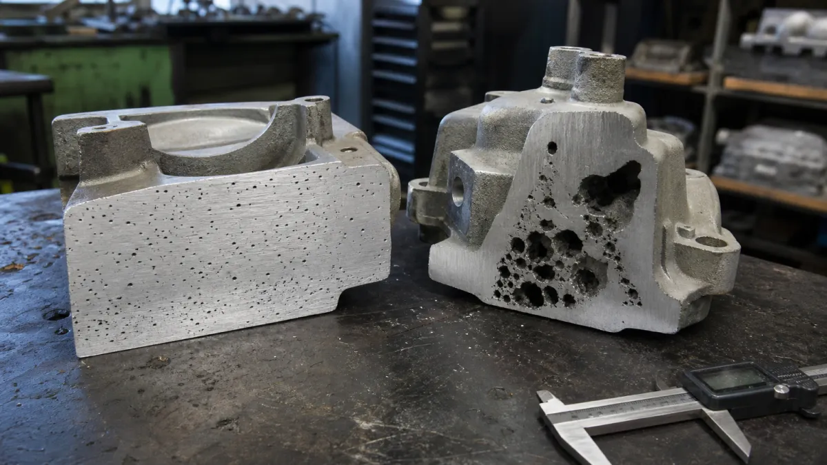
Gas porosity appears as small, round, smooth-walled pores inside the casting. The gas has three main sources: air entrained by a turbulent metal front during filling, water vapor from excess die lubricant flashing to steam, and hydrogen dissolved in the melt coming out of solution as the metal solidifies. Pores concentrate near the gate area and in sections that fill last.
Fixes target each source: a shot profile that keeps the metal front below the turbulence threshold until the cavity is nearly full, properly sized vents and vacuum assist where needed, a controlled minimum of die spray, and sound melt practice with clean charge material, controlled holding temperature, and degassing where hydrogen is a recurring problem.
Shrinkage Porosity
Shrinkage porosity forms when solidifying metal cannot draw feed metal from a neighboring section. Aluminum and zinc alloys shrink several percent by volume as they solidify, and the last regions to freeze, usually thick sections, junctions, and thermal hot spots, end up with irregular, angular voids. Unlike gas pores, shrinkage voids have rough, dendritic walls.
Fixes include intensification pressure high enough to feed the hot spot, a gate and runner sized to stay liquid until the cavity freezes, die cooling balanced to pull heat out of heavy sections, and, most effective of all, a part design without isolated thick masses.
| Feature | Gas Porosity | Shrinkage Porosity |
|---|---|---|
| Pore shape | Round, smooth-walled | Irregular, angular, dendritic |
| Typical location | Near gate, last-to-fill regions | Thick sections, thermal centers |
| Root cause | Entrained air, vapor, dissolved hydrogen | Inadequate feeding during solidification |
| Primary fix | Shot profile, venting, melt practice | Intensification pressure, gate design, cooling balance |
Reading the pore shape on a fracture surface or X-ray image is the fastest way to separate the two, and the repair path is different for each.
Inclusions
Inclusions are non-metallic particles trapped in the casting: oxide films folded in during filling, sludge particles (hard iron-aluminum-manganese intermetallics that form in holding furnaces running too cold), and occasional refractory or lubricant residue. Inclusions act as crack initiation sites under load and appear as hard spots that destroy tool edges during machining.
Prevention is melt discipline: keep holding furnace temperature above the sludge formation range, skim and clean transfer ladles, verify alloy chemistry on every ingot lot, and limit melt turbulence at the ladle and shot sleeve. On the die side, a runner layout that avoids folding the metal front over itself removes most oxide-film defects.
Surface Die Casting Defects
Cold Shut and Short Fill
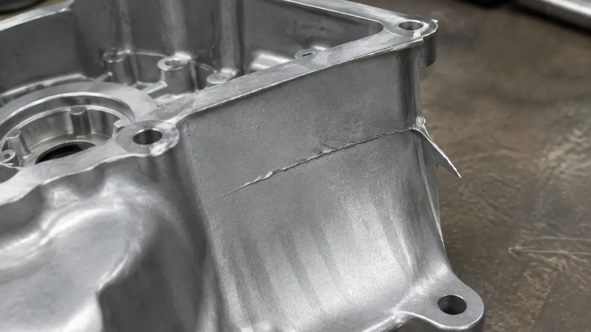
A cold shut is a visible line or crease where two metal fronts met but failed to fuse because they had cooled too far. Short fill, also called misrun, is the same mechanism taken further: the metal freezes before the cavity is complete and the part comes out missing features. Both point to heat loss, from metal or die temperature too low, fill time too long, walls too thin for the flow length, or blocked vents raising back pressure.
Fixes start with bringing die temperature into its operating window and shortening fill time. If the defect persists, the gate location and flow path need review so that fronts converge in non-critical areas, or the wall thickness needs a local increase.
Flow Marks
Flow marks are streaks or bands on the surface following the fill direction, caused by metal that partially solidifies against the die wall before the cavity is full. They are cosmetic on most parts but unacceptable on plated or Class A surfaces. Low die temperature, excessive spray, and slow fill are the usual causes, and the fix is thermal balance and fill speed rather than more polishing.
Blisters
Blisters are raised bubbles on the surface that appear after ejection or, worse, after powder coating or paint curing, when trapped subsurface gas expands with heat. They indicate gas porosity close to the skin of the casting. Reducing entrained air through the shot profile, venting, and spray control is the cure, and parts destined for high-temperature coating should carry porosity limits verified by X-ray sampling.
Cracks and Hot Tearing
Hot tears open while the casting is still semi-solid and too weak to resist contraction stresses, typically at sharp internal corners, section changes, or around inserts. Cold cracks appear after solidification, usually at ejection when the part hangs on undercuts or sticks to the die. Generous fillets, uniform wall transitions, adequate draft, and balanced ejection are the design-side fixes, while die temperature balance and alloy cleanliness cover the process side.
Heat Checking
Heat checking is a network of fine cracks on the die surface caused by thermal fatigue, and it prints onto every part the die makes. Aluminum dies are the most exposed because of the high casting temperature. Quality H13 die steel, proper preheating before production, balanced cooling, and surface treatments such as nitriding slow it down. Once the checks are deep, the cavity needs welding and re-machining, which is a tooling decision rather than a parameter tweak.
Flash
Flash is a thin fin of metal forced into the parting line, slide gaps, or ejector pin clearances. The direct cause is metal pressure exceeding the die's ability to stay closed: insufficient clamping tonnage for the projected area, worn or damaged parting surfaces, debris on the die face, or injection pressure set higher than the process needs. Verify the tonnage calculation first, then the die condition. Trimming flash hides the symptom; it does not fix the cause.
Soldering and Drag Marks
Soldering is aluminum chemically welding itself to the die steel under high gate velocity, high temperature, or insufficient release agent, after which the part tears on ejection and the die needs stoning. Drag marks are scratches in the ejection direction from inadequate draft, rough cavity surfaces, or misaligned ejectors. Manganese-modified alloys and die coatings reduce soldering tendency; honest draft angles and polished draw surfaces prevent drags.
Dimensional and Shape Defects
Deformation and Warpage
Warpage appears after ejection or cooling, when residual stress, uneven section thickness, or unbalanced die temperatures pull the part out of shape. Long flat parts and thin-walled housings are the most sensitive. Uniform walls, ribs for stiffness, balanced cooling channels, and a flat, supported ejection layout control most of it, and severe cases deserve a stress discussion at the DFM stage rather than a straightening fixture at the end of the line.
Mismatch and Parting-Line Shift
Mismatch is a step between the two die halves on the finished part, caused by worn guide pins, thermal expansion differences, or platen parallelism problems on the machine. It consumes machining stock and can scrap precision features. Treat it as a maintenance signal: measure the step, then repair the die alignment instead of compensating downstream.
How Are Die Casting Defects Detected and Inspected?
Surface defects are caught at the machine by visual inspection under defined lighting, with fluorescent penetrant testing reserved for crack-sensitive parts. Internal defects need indirect methods: X-ray inspection reveals porosity distribution and inclusions, and CT scanning maps pores in three dimensions when a failure analysis justifies it. Pressure-decay leak testing is the practical gate for housings that must hold air or fluid, because it tests function rather than appearance. Dimensional deviations go to the coordinate measuring machine.
| Defect Category | Typical Defects | Detection Method |
|---|---|---|
| Surface | Cold shut, flash, cracks, flow marks | Visual inspection, fluorescent penetrant |
| Internal | Gas and shrinkage porosity, inclusions | X-ray, CT scanning, sectioning |
| Leakage | Subsurface porosity connecting to the surface | Air pressure-decay leak testing |
| Dimensional | Warpage, mismatch, feature position | Coordinate measuring machine (CMM) |
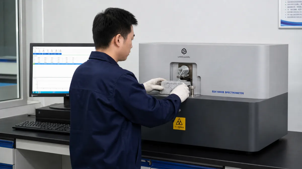
| Material | Off-chemistry melts, sludge-forming conditions | Spectrometer verification per ingot lot |
Inspection works best as prevention rather than sorting. In our plant, every ingot lot is verified by spectrometer before it reaches the furnace, porosity-critical parts are X-ray sampled by cavity, and dimensional first articles run on a Zeiss CMM, the same inspection stack described in our quality inspection and testing capabilities. Catching a drifting parameter at the first article costs minutes; catching it at customer assembly costs the shipment.
Process Parameters That Cause (and Prevent) Defects
Most recurring defects are parameter problems wearing a disguise. The table below maps the main process parameters to the defects they produce when they drift out of window.
| Parameter | Out-of-Window Behavior | Typical Defects |
|---|---|---|
| Die temperature (aluminum: roughly 180-280 C) | Too cold: premature freezing; too hot: soldering, long cycles | Cold shut, flow marks, soldering |
| Metal temperature at shot (aluminum: roughly 660-710 C) | Too cold: cold shuts and sludge; too hot: gas absorption, shrinkage | Cold shut, gas porosity, shrinkage |
| Slow shot speed | Too fast: turbulence before the gate; too slow: premature freezing | Gas porosity, cold shut |
| Gate (fast shot) speed, often 25-60 m/s | Too fast: atomization, air entrainment, die erosion; too slow: cold laps | Gas porosity, cold shut, flow marks |
| Intensification pressure | Too low: unfed shrinkage; too high: flash and die stress | Shrinkage porosity, flash |
| Die lubricant and spray | Too much: steam porosity and stains; too little: soldering and drags | Blisters, gas porosity, soldering |
| Cycle time | Too short: die overheats; too long: die chills | Heat checking, cold shut |
These parameters interact, which is why single-knob tuning often moves a defect instead of removing it. We run JSCAST flow simulation on every new mold before steel is cut, predicting air entrapment zones and shrinkage hot spots so the gate, vents, and cooling channels are positioned correctly at the design stage, the same simulation-driven approach described in our die casting mold design guide. Simulation does not replace parameter discipline, but it means the process window is already wide before the first shot.
Design (DFM) Rules That Prevent Die Casting Defects
A defect prevented in CAD costs nothing. Each design rule below exists to prevent a specific defect from the sections above:
- Keep wall thickness uniform (typical aluminum: 2-3 mm; zinc: 0.8-1.5 mm) to prevent shrinkage porosity and warpage
- Replace sharp internal corners with fillets to prevent hot tearing and cracks
- Use ribs and bosses instead of thick sections to prevent sinks and shrinkage voids
- Give every draw surface adequate draft to prevent drag marks and ejection cracks
- Place the parting line away from cosmetic and precision faces to limit flash and mismatch damage
- Design flow length and gate position so metal fronts converge in non-critical areas to prevent cold shut in visible or stressed zones
- Reserve space for vents and overflows at last-to-fill points to prevent gas porosity and short fill
Full dimensional recommendations, tolerance grades, and wall thickness tables are in our aluminum die casting design guide. The short version: send the 3D model before the design freezes, because changing a fillet in CAD is free and changing it in hardened H13 is not.
Aluminum vs Zinc Die Casting Defects: What Changes?
Aluminum runs in cold chamber machines at melt temperatures around 660-710 C, while zinc runs in hot chamber machines around 420 C. That temperature gap changes which defects dominate, and the table below summarizes the practical differences.
| Aspect | Aluminum (Cold Chamber) | Zinc (Hot Chamber) |
|---|---|---|
| Dominant internal risk | Gas and shrinkage porosity in thick sections | Less shrinkage-driven; thin walls freeze fast and uniformly |
| Die attack | Soldering and heat checking are constant threats | Far less soldering; dies often run past a million shots |
| Typical surface issues | Flow marks, solder tears, hot tearing at corners | Flow marks on thin cosmetic parts; blisters appear at plating if subsurface gas exists |
| Chemistry-driven defects | Sludge inclusions from cold holding furnaces | Intergranular corrosion (zinc pest) from lead, cadmium, or tin impurities, eliminated by certified high-purity Zamak |
| Design sensitivity | Wall thickness and feeding of heavy sections | Very thin walls magnify flow-path and venting errors |
The practical takeaway: an aluminum program lives or dies on thermal balance and feeding, while a zinc program lives or dies on flow-path design and alloy purity. Process and design details for the zinc side are in our zinc die casting design guide.
Die Casting Defects Quick Reference: Cause and Fix Matrix
Use this matrix to move from a defect you can see to the cause worth checking first.
| Defect | Class | Most Likely Cause | First Fix to Try | First Detection Method |
|---|---|---|---|---|
| Gas porosity | Internal | Turbulent filling, vapor, hydrogen | Shot profile and venting, melt practice | X-ray |
| Shrinkage porosity | Internal | Unfed hot spots | Intensification pressure, cooling balance | X-ray, sectioning |
| Inclusions | Internal | Melt sludge, folded oxides | Furnace temperature discipline, melt cleaning | Machining, spectrometer trend |
| Cold shut | Surface | Heat loss before fronts fuse | Die temperature, fill time | Visual |
| Flow marks | Surface | Partial freezing at the die wall | Thermal balance, fill speed | Visual |
| Blisters | Surface | Subsurface gas expanding with heat | Reduce entrained air, X-ray screen before coating | Visual after cure, X-ray |
| Cracks and hot tearing | Surface | Contraction stress at corners | Fillets, die temperature balance | Visual, penetrant |
| Heat checking | Surface (die-origin) | Die thermal fatigue | Die preheat, cooling balance, steel quality | Visual pattern on part |
| Flash | Surface | Metal pressure exceeds die closure | Tonnage check, die face condition | Visual |
| Soldering and drag marks | Surface | Die attack or poor draft | Release practice, coatings, draft angles | Visual |
| Deformation and warpage | Dimensional | Residual stress, unbalanced cooling | Uniform walls, cooling balance | CMM, checking fixtures |
| Mismatch and parting-line shift | Dimensional | Die alignment wear | Die maintenance, guide pins | CMM, visual step check |
Most defect investigations we run for customers end at one of three places: die thermal balance, the shot profile, or a wall thickness decision locked in at design time. Catching these early costs engineering hours; catching them in mass production costs shipments. Meituo operates 20 aluminum die casting machines from 160T to 1650T with annual output near 10,000 tons, validates every new mold with JSCAST flow simulation, verifies every ingot lot by spectrometer, and inspects under an IATF 16949 quality system with X-ray and Zeiss CMM equipment. If porosity limits, leak requirements, or cosmetic standards matter on your next program, send the part drawing and specifications, and our engineering team will return a DFM review with a process recommendation.