How tight a tolerance can a die casting hold? For most aluminum and zinc parts, the NADCA standard answer is ±0.010 in (±0.25 mm) on the first inch, plus ±0.001 in (±0.025 mm) for each additional inch — and that is before parting lines, slides, and geometry add their share. Precision-grade tooling cuts the linear component to ±0.002 in (±0.05 mm) on the first inch. This guide explains the NADCA tolerance system with its full value charts in inches and millimeters, walks through a complete calculation example, and clarifies when a feature should be machined instead of cast to size.
What Tolerances Can Die Casting Hold? (Quick Answer)
Under the NADCA Product Specification Standards for Die Castings, linear dimensions formed within one die half hold ±0.010 in (±0.25 mm) on the first inch plus ±0.001 in per additional inch at the Standard level, and ±0.002 in (±0.05 mm) plus ±0.001 in per additional inch at the Precision level, for zinc, aluminum, and magnesium alloys. Dimensions crossing the parting line or formed by moving die components carry additional allowances on top of these values.
| Alloy | Standard Level (first inch + each add. inch) | Precision Level (first inch + each add. inch) |
|---|---|---|
| Zinc | ±0.010 in (±0.25 mm) + ±0.001 in (±0.025 mm) | ±0.002 in (±0.05 mm) + ±0.001 in (±0.025 mm) |
| Aluminum | ±0.010 in (±0.25 mm) + ±0.001 in (±0.025 mm) | ±0.002 in (±0.05 mm) + ±0.001 in (±0.025 mm) |
| Magnesium | ±0.010 in (±0.25 mm) + ±0.001 in (±0.025 mm) | ±0.002 in (±0.05 mm) + ±0.001 in (±0.025 mm) |
| Copper | ±0.014 in (±0.36 mm) + ±0.003 in (±0.076 mm) | ±0.007 in (±0.18 mm) + ±0.002 in (±0.05 mm) |
These are process capability values for production tooling, not the best a single sample can achieve. In practice, zinc's fluidity and low casting temperature let well-maintained dies hold tighter results on small parts; some die casters quote ±0.001–0.002 in for zinc and ±0.002–0.004 in for aluminum as their practical ceiling. Treat anything tighter than Precision grade as a machining conversation, not a casting promise.
NADCA vs ISO 8062: Which Standard Applies to Your Drawing?
Two tolerance systems appear on die casting drawings. NADCA's Product Specification Standards dominate North American programs and define two achievement levels: Standard, the most economical level for normal production, and Precision, which requires extra die accuracy and tighter process control at added cost. ISO 8062-3 is common on European and international drawings and expresses capability through DCTG (Dimensional Casting Tolerance Grades). For high-pressure die casting, typical grades are DCTG 5–7 for aluminum and magnesium, and DCTG 4–6 for zinc.
| NADCA | ISO 8062-3 | |
|---|---|---|
| Typical use | North American drawings and suppliers | European and international drawings |
| Grading system | Standard / Precision two levels | DCTG grades (typical HPDC: 5–7 Al/Mg, 4–6 Zn) |
| Native units | Inches (metric equivalents published) | Millimeters |
| Structure | Linear + projected-area additions by feature type | Grade value by nominal dimension range |
When a drawing is silent, the supplier's regional default applies, so state the standard explicitly at RFQ. Mixing the two systems on one drawing is a common source of quoting disputes.
How NADCA Tolerances Work: Linear Plus Projected Area
The NADCA system builds every feature tolerance from two components. The linear component covers growth, shrinkage, and minor imperfection along the dimension itself. The projected-area component covers the extra variation that appears when a dimension depends on how tightly the die closes or how consistently a slide seats: molten metal pressure pushes the die halves apart by a small amount, and that movement scales with the area over which the pressure acts.
Three feature types follow from this logic. A feature machined entirely within one die half carries only the linear tolerance. A dimension that crosses the parting line, such as overall thickness, adds a projected-area allowance on the positive side only, because die separation can only make the casting thicker. A feature formed by a moving die component, such as a slide or core pull, adds its own allowance based on the slide's projected area. Understanding which type each dimension belongs to is the first step in any tolerance review.
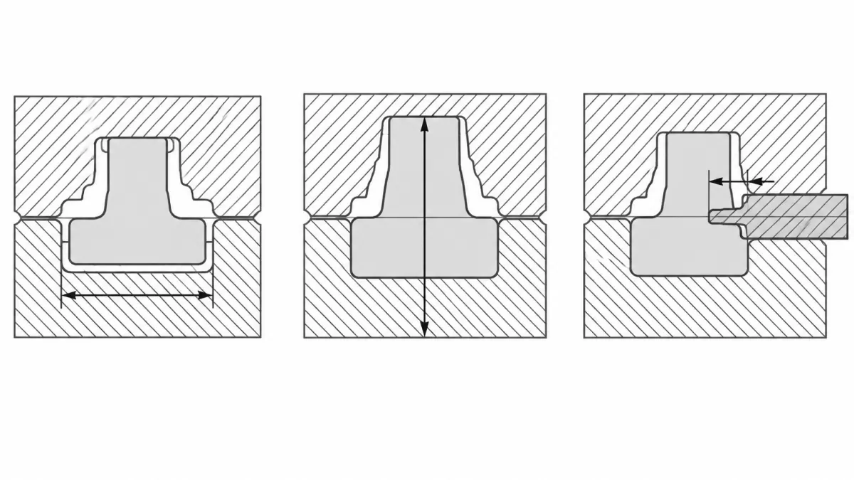
Left: dimension within one die half — linear tolerance only | Center: dimension across the parting line — adds a projected-area allowance | Right: dimension formed by a moving core — adds a slide allowance
NADCA Die Casting Tolerance Charts (Inches and Millimeters)
The charts below are transcribed from NADCA Product Specification Standards for Die Castings, Section 4A (Coordinate Dimensioning). Values are given in inches with millimeter equivalents.
Linear Dimensions (Standard & Precision)
Applies to features formed within one die half, without moving components. The worked example in the standard: a 5.00 in aluminum feature holds ±0.014 in (±0.35 mm) at Standard level and ±0.006 in (±0.15 mm) at Precision level.
Dimensions Across the Parting Line
Added to the linear tolerance, on the positive side only, based on the projected area of the casting at the parting plane:
| Projected Area | Zinc Standard | Zinc Precision | Al/Mg Standard | Al/Mg Precision |
|---|---|---|---|---|
| up to 10 in² (64.5 cm²) | +0.0045 in (+0.114 mm) | +0.003 in (+0.076 mm) | +0.0055 in (+0.14 mm) | +0.0035 in (+0.089 mm) |
| 11–20 in² (71–129 cm²) | +0.005 in (+0.13 mm) | +0.0035 in (+0.089 mm) | +0.0065 in (+0.165 mm) | +0.004 in (+0.102 mm) |
| 21–50 in² (135–323 cm²) | +0.006 in (+0.15 mm) | +0.004 in (+0.102 mm) | +0.0075 in (+0.19 mm) | +0.005 in (+0.153 mm) |
| 51–100 in² (329–645 cm²) | +0.009 in (+0.23 mm) | +0.006 in (+0.153 mm) | +0.012 in (+0.30 mm) | +0.008 in (+0.203 mm) |
| 101–200 in² (652–1290 cm²) | +0.012 in (+0.30 mm) | +0.008 in (+0.203 mm) | +0.018 in (+0.46 mm) | +0.012 in (+0.305 mm) |
| 201–300 in² (1297–1936 cm²) | +0.018 in (+0.46 mm) | +0.012 in (+0.305 mm) | +0.024 in (+0.61 mm) | +0.016 in (+0.406 mm) |
Above 300 in², values are negotiated with the die caster. Note the asymmetry: because die separation only adds metal, the allowance appears on the plus side only.
Dimensions Formed by Moving Die Components
Slides and core pulls add a similar positive-side allowance, scaled by the projected area of the moving component's head. At Standard level, zinc adds +0.006 in for small components up to +0.032 in at 201–300 in²; aluminum and magnesium run slightly wider, from +0.008 in up to +0.040 in. Precision level trims roughly a quarter to a third off each value. Slide condition and locking design directly control this allowance, which is one reason die casting mold design decisions and achievable tolerances are the same conversation.
Flatness and Angularity
Flatness is measured on the maximum surface dimension (diameter for round faces, diagonal for rectangular ones): Standard allows 0.008 in (0.20 mm) for the first 3 in plus 0.003 in per additional inch; Precision allows 0.005 in plus 0.002 in per additional inch. A 10 in diagonal therefore permits 0.029 in at Standard and 0.019 in at Precision. Flatness is independent of thickness tolerance and the two never stack.
Angularity (covering parallelism and perpendicularity of surfaces) depends on where the two surfaces sit relative to the die: within one die half, Standard is 0.005 in for the first 3 in plus 0.001 in per additional inch; across the parting line it rises to 0.008 in plus 0.0015 in; and surfaces involving moving components can reach 0.011 in plus 0.003 in. A 7 in surface checked for parallelism across the parting line at Standard level allows 0.014 in (0.36 mm).
Concentricity and Parting-Line Shift
Concentricity (measured as T.I.R.) within one die half allows 0.008 in for diameters up to 3 in, plus 0.002 in per additional inch of diameter. Across the parting line, the allowance is set by cavity projected area, from +0.008 in up to 50 in² to +0.022 in at 201–300 in². Parting-line shift — the lateral mismatch between die halves — carries its own ± table: ±0.004 in up to 50 in², rising to ±0.025 in at 801–1200 in². Both values exist at Standard level only; if either is critical, design around it or plan machining.
Draft Allowances (C Constants)
NADCA expresses draft through a constant C, where draft depth D = L / C for Standard tooling (L is the feature depth), and the corresponding angle is A = 57.2738 / (C × √L). Interior walls need roughly twice the draft of exterior walls, because the solidifying casting shrinks onto cores and away from cavity walls.
| Feature | Zinc/ZA | Aluminum | Magnesium | Copper |
|---|---|---|---|---|
| Inside walls (Standard C) | 50 | 30 | 35 | 25 |
| Outside walls (Standard C) | 100 | 60 | 70 | 50 |
| Holes, total draft (Standard C) | 34 | 20 | 24 | 17 |
For an aluminum inside wall, a 1.0 in depth gives 0.033 in of draft, about 1.9 degrees. Precision-grade tooling raises the C constants (for aluminum, 40 inside and 80 outside), which roughly halves the draft.
Worked Example: Tolerance Stack-Up on a 5-Inch Aluminum Housing
Take an aluminum housing whose 5.00 in overall thickness crosses the parting line, with a projected parting area of 75 in². The calculation runs in three steps:
- Linear component, Standard level: ±0.010 in for the first inch, plus 4 × ±0.001 in, gives ±0.014 in.
- Parting-line component: 75 in² falls in the 51–100 in² band, adding +0.012 in on the positive side only.
- Combined tolerance on the 5.00 in dimension: +0.026 / −0.014 in (+0.65 / −0.35 mm).
At Precision level the same dimension calculates to +0.014 / −0.006 in. If the housing also has a boss formed by a slide, that boss dimension stacks its own moving-component allowance on top, using the slide head's projected area rather than the part's. This additive structure is why dimensions that matter should be designed within one die half whenever the geometry allows it.
As-Cast vs CNC Machining: When to Machine a Feature
Cast to size when the Standard or Precision chart meets the functional requirement. Machine when the feature needs bearing-seat accuracy, thread quality, sealing flatness, or anything tighter than Precision grade. NADCA's rule for the machining allowance is a minimum of 0.010 in (0.25 mm) of stock, with the maximum set by adding the machining variable and the applicable casting tolerances; keeping the datum and the machined feature in the same die half keeps that allowance small. Excessive stock wastes cycle time and can cut into the dense, fine-grained skin of the casting, exposing subsurface porosity.
On our side, first-article dimensions are verified on a Zeiss CMM and porosity-critical features are checked by X-ray before ramp-up, and the same machining and inspection capabilities handle features that must go tighter than cast tolerances.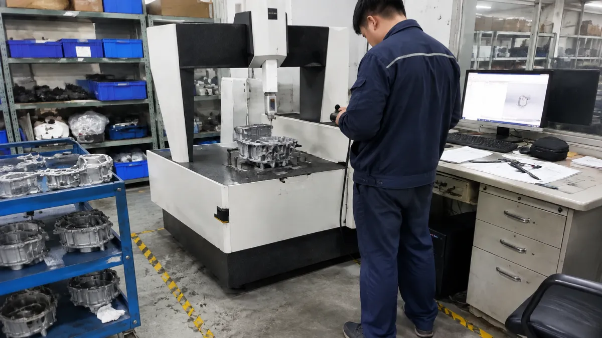 The decision is made at DFM, not after the die is cut.
Aluminum vs Zinc Die Casting Tolerances
The NADCA charts give zinc smaller allowances than aluminum at every feature type beyond the basic linear value — a consequence of zinc's lower casting temperature, higher fluidity, and the hot-chamber process. Two zinc-specific notes matter for specification. Zinc castings can undergo slight dimensional growth over time from creep and aging, so NADCA recommends artificial aging (a low-temperature heat treatment) to stabilize critical dimensions on precision zinc parts. And miniature zinc components follow a separate standard section with tighter values than the general charts.
| Feature (Standard level) | Zinc | Aluminum |
|---|---|---|
| Linear, first inch | ±0.010 in (±0.25 mm) | ±0.010 in (±0.25 mm) |
| Across parting line, 51–100 in² | +0.009 in (+0.23 mm) | +0.012 in (+0.30 mm) |
| Moving die component, small slide | +0.006 in (+0.15 mm) | +0.008 in (+0.20 mm) |
| Draft constant C, inside wall | 50 | 30 |
For zinc-specific design values including wall thickness and miniaturization, our zinc die casting design guide covers the design side in detail.
Design Tips: Don't Over-Tolerance Your Castings
The cheapest tolerance is the one you do not tighten. Three rules keep drawings economical:
- Open up every dimension that does not affect fit, form, or function; each dimension tightened to Precision grade adds die cost, maintenance, and scrap risk.
- Concentrate tight requirements on a few critical features and put them in the same die half as their datum.
- Review the tolerance stack with the die caster before freezing the design; moving a parting line or a slide at the drawing stage is free, and our aluminum die casting design guide covers the related wall thickness and draft recommendations.
Meituo runs 20 aluminum die casting machines from 160T to 1650T with in-house mold making, machining, and finishing under one roof, and verifies dimensions on Zeiss CMM equipment under an IATF 16949 quality system. If you have a drawing with tolerance questions, send it with your annual volume and we will return a DFM review with the achievable tolerance for each critical feature.